Relative Scuffing Load Carrying Capacity Tester
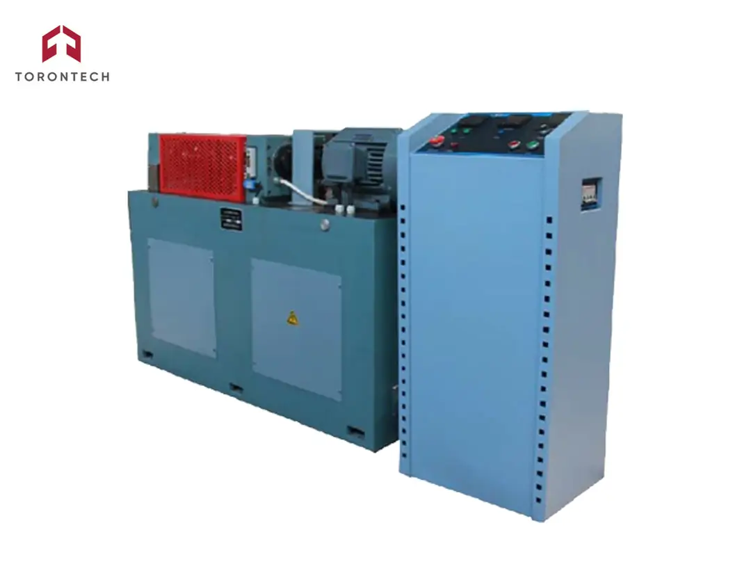
Relative Scuffing Load Carrying Capacity Tester TT-FZG
Relative Scuffing Load Carrying Capacity Tester TT-FZG conforms to ISO 14635-1 Gears – FZG test procedures—Part 1: FZG test method A/8, 3/90 for relative scuffing load-carrying capacity of oils, and ISO 14635-2 – FZG test method A10/16,6R/90 for relative scuffing load-carrying capacity of lubricants with high EP performance.
Gear failures that may be influenced by the lubricant include scuffing, low-speed wear, and gear-surface fatigue phenomena such as micropitting and pitting. These types of gear damage are considered in the gear design process by using specific lubricant and service-related characteristic values. Accurate, field-related selection of these values requires adequate lubricant test procedures. The FZG test procedures outlined in this and other parts of ISO 14635 serve as tools to determine the lubricant-related characteristic values for calculating the load-carrying capacity of gears.
The FZG test method A/8, 3/90 for the relative scuffing load-carrying capacity of oils, described in this part of ISO 14635, is typical for most applications in industrial and marine gears. ISO 14635-2 pertains to the relative scuffing load-carrying capacity of oils with very high EP properties, used for lubricating automotive driveline components.
The tester consists of two separate parts: the main unit and the electric control cabinet.
The main unit uses a dynamic closed-loop structure (or power flow closed structure) and uses a weight-hanging method on the loading rod for loading. It has a horizontal design and should be placed on level ground. The lower part is the machine base, which features two gear cases on its upper plane. Between the two gear cases are two sets of parallel rotating shafts and torsion shafts, along with a loading clutch and a torque measuring clutch.
The left gear case is the test gear case, housing a pair of high-precision test gears of different sizes. The case's left cover and top cover can be opened for easy loading and unloading of the test gears. The right gear case is the transmission gear case, also containing a pair of high-precision transmission gears of different sizes. Each gear is mounted on a different shaft with a key joint, supported by two pairs of deep groove ball bearings, and mounted on the left and right gearboxes.
On the right side of the transmission gearbox is the testing machine's driving motor, which features a compact structure, high precision, and stable performance.
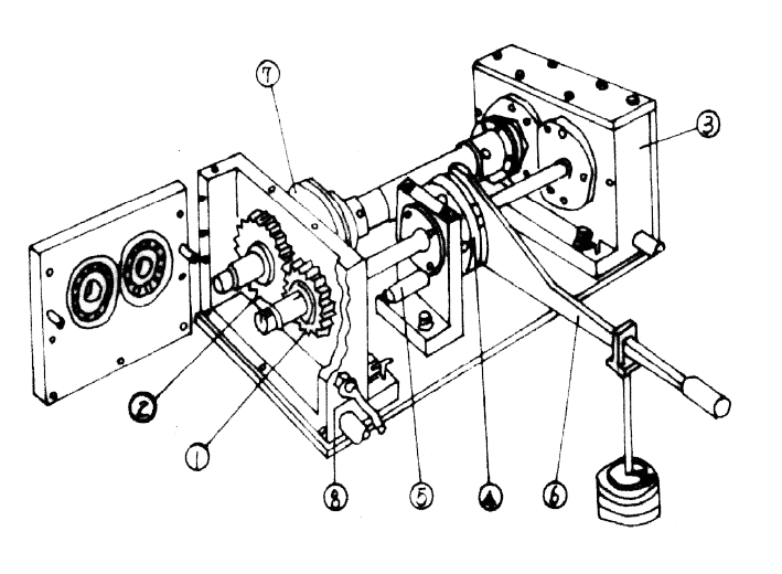
1. Small test gear
2. Big test gear
3. Transmission gear case
4. Loading clutch
5. Fixed pin
6. Lever arm with weights
7. Torque measuring clutch
8. Temperature sensor
Loading method
The loading rod is hung on the sheave of the loading clutch. After adding weights, tighten the two sheaves on the loading clutch by tightening the nut of the loading clutch. Then, remove the weights and the loading rod. The torque value can be read on the torque measuring clutch.
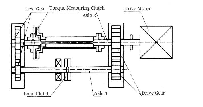
The drive motor YD132M-4/2 is a two-speed motor that drives the transmission gear via the shaft to transmit torque to the test gear. The test gear is housed in a test gear case, which can hold various liquid test mediums. The test gear portion is immersed in the test medium for testing purposes.
Electric cabinet and control panel
The electric control cabinet comprises four parts: the control cabinet body, the control panel, the strong current system, and the weak current system. The control panel, situated above the cabinet, is easily operable, while the cabinet interior is equipped with the strong current system. A rear door allows access to the internal system for installation, debugging, and maintenance purposes.
The control panel is divided into three parts: upper, middle, and lower. The lower part features control switches and alarms, while the middle section contains switches for heating, cooling, and motor speed selection. The upper portion includes a temperature controller, time controller, and revolution controller. The time display and control unit allow selection of control time within the range of 1s to 9999min. A CLEAR button beneath the control unit clears the digital display window.
The revolution display and control unit permit selection of control revolution speed within the range of 1 to 99999999.
Torque measuring clutch
The torque measurement clutch device, depicted in Fig.4, primarily consists of:
1. Small connecting flange (1)
2. Large connecting flange (2)
3. Torque shaft (3) within the outer tube (4)
4. Indicating flange (5) with Vernier caliper scale (6)
5. Scale (7) on the large connecting flange (2)
Upon loading, the elastic shaft (3) within the closed-loop system of the tester undergoes twisting and deformation. The "torque" can then be read using the Vernier caliper scale.
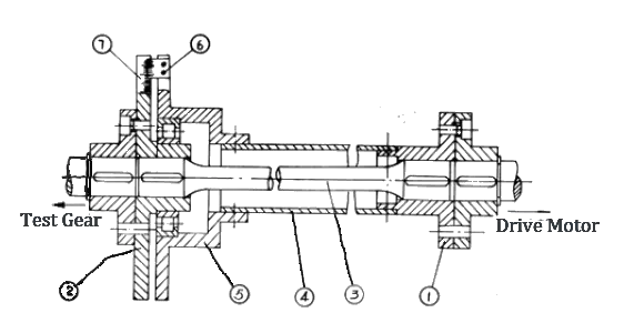
1. Small flange
2. Big flange
3. Torsion bar
4. Outer tube
5. Indicating flange with vernier caliper
6. Vernier caliper
7. Scale
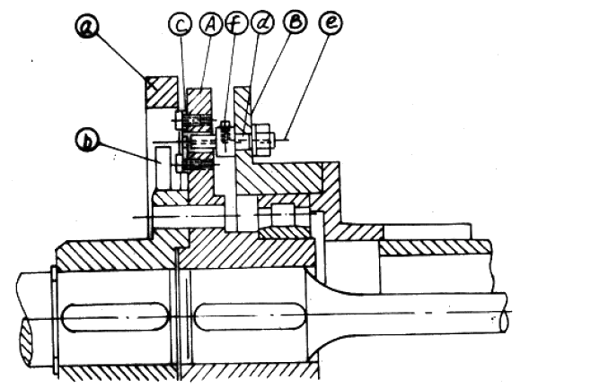
This tester features a gear tooth broken control device, as illustrated in Fig.5.
During testing, if the gear breaks or if there is an abnormal increase in load on the gear, the overload automatic protection device will halt the test automatically.
The protection device comprises:
- Copper ring (a)
- Flat spring (b)
- Shear sheet (c)
- Pinhole (d)
- Shear pin (e)
The copper ring (a) is mounted on the bottom plate of the testing machine but is insulated from it. After loading, adjust the position of the pinhole on the groove of the torque measuring clutch (B) so that it aligns with the appropriate position corresponding to the shear hole (d). In this position, the shear pin can pass through the shear plate and pinhole. While performing this task, press down the flat spring (b) with the needle (the flat spring protrudes from the copper ring) and secure the shear pin in place with the screw (f).
If there is an abnormal change in torque, the indicating flange (5) and the large flange on the torque measuring clutch will rotate relative to each other, causing the shear pin to shear the shear sheet. The flat spring (b) immediately contacts the copper ring (a), closing a contact in the control circuit and stopping the drive motor instantaneously.
1. Maximum torque: 1kN·m
2. Maximum load class: Grade 13
3. Temperature accuracy: ±2℃
4. Drive motor power: 6.5kW (8kW)
5. Revolution speed: 1450rpm / 2880rpm
6. Test gear case capacity: 1.25L (measured from the center line of the shaft to the bottom of the case)
7. Heating power: 0.5kW * 3 = 1.5kW
8. Test time control range: 1s - 9999min
9. Revolution range: Up to 9999999
10. Main host Dimensions: 1390mm * 750mm * 1082mm
11. Control cabinet dimensions: 510mm * 510mm * 1040mm
12. Test gear specifications:
- Modules: 4.5
- Number of teeth: Zb=24, Zs=16
- Modification coefficient: Xb=-0.5, Xs=0.08532
- Engaging angle: 22°26’
- Central moment: 91.5mm
- Accuracy grade: 5
Standard Configuration
1. Main host: 1 set
2. Control cabinet: 1 set
3. Dedicated tools: 1 set
4. Lever arm and weights: 1 set
5. Oil spray source (optional)
6. Cooling system (optional)
7. A-type test gear (optional)